Examining the First Mechanical Calculator
Uncategorized
1
Posts
1
Posters
0
Views
-
Examining the First Mechanical Calculator
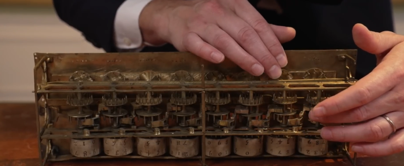
Blaise Pascal is known for a number of things, but we remember him best for the Pascaline, an early mechanical calculator. [Chris Staecker] got a chance to take a close look at one, which is quite a feat since there were only about 20 made, and today we only know where nine of them wound up.
This Pascaline was lost for many years, and turned up in an antique store, where they thought it was a music box of some kind. The recent owner passed away, and now this machine is going to go up for auction, probably for more than we can afford. While he wasn’t able to handle the antique, he has plenty of knock-offs that were made back when people actually used them, which wasn’t that long ago. One of these is transparent, so you can see the mechanism inside.
The idea is to use the wheels like an old-fashioned phone dial to add counts to an output wheel. A linkage moves the next input wheel every time the current output wheel passes nine. Of course, if you have a multi-digit carry, it might take a little more elbow grease than just flipping the dial one normal position.
The Pascaline could subtract, too, but modern versions use a more efficient method. Pascal was worried about the extra elbow grease required to push the carry, and the Pascaline actually stored energy to drive the carry mechanism. Pretty forward-thinking for someone building the very first mechanical calculator.
This Pascaline was unusual because it was made for surveying and used old French units. If it were made today, for example, it would have inch wheels that would carry a foot when they went past 11.
What a beautiful machine. You’d like to think that if you lived in the 1650s, you’d dream up this machine. But, to be honest, we probably wouldn’t. We can’t say anything about you.
We’ve seen Pascaline machines before, of course. While we love complex mechanical computers, there’s a certain charm to the simple ones, too.
youtube.com/embed/CROrLQpN6dc?…
Gli ultimi otto messaggi ricevuti dalla Federazione
-
@hipsterelectron I wonder how many CVEs have been filed against the CVE website
-
OF COURSE THE CVE WEBSITE DOESN'T WORK ON FIREFOX
-
why is it "oh grow up!" and not "get down on my hormonal level will you?"
-
-il suo livello di napoletano?
-eccellente!
-allora mi traduca "sembra il mio amico proveniente dalla capitale francese"
-par is!
-
Building a Hydraulic Gear Pump Isn’t So Easy
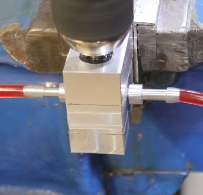
The gear pump prototype in action. (Credit: Artisan Makes, YouTube)
Hydraulic gear pumps are deceptively simple: just two gears rotating together, forcing the hydraulic oil from one side to the other where the teeth don’t meet, and thus providing the ability to pressurize said oil to make hydraulic cylinders, final drives, etc. do their thing. As with most machining projects like this, the devil is absolutely in the details, particularly in the tolerances. This is the crash course that the [Artisan Makes] channel on YouTube is currently going through.In this part one of a series on a DIY gear pump, scrap aluminium is used for the housing, along with 1045 medium carbon steel for the gears and W1A high carbon steel for bearings and other wear surfaces. Since at least one of the gears needs to be driven, a lip seal rated for 10 bar is used to provide a path for the shaft. As noted in the video, this is supposed to be a learning experience, ergo it’s a simplified design that merely targets being functional as a gear pump.
With the basic design figured out, the parts were created on the lathe and mill, followed by assembly. Most of the controversy is about the tolerances within the housing, as any leakage will reduce the efficiency. This means the spacing between the gears and housing, space between the gears and bearings, as well as that provided by the gasket that seals the housing base and top. This is where the comment section somewhat explodes with criticism and advice.
As can be seen in the demonstration with a better gasket, there is absolutely flow when driven at 1200 RPM, but also clearly severe leakage as evidenced by said flow not moving quite as fast as it should. We’re looking forward to the next part, in which addressing these tolerances is tackled, with hopefully a much more performant gear pump resulting.
-
Che poi, spacciano per Made in Italy ciò che non lo è, ma il vero Made in Italy costa. Gli italiani, in massa, hanno perso la capacità di capire la qualità, quindi vanno di schifezze a prezzi bassissimi. Il Casentino ti dura una vita ma costa. Quando avranno capito che il low cost non esiste perché qualcuno il prezzo lo paga, la filiera italiana sarà morta e sepolta. Amen.
-
@Linkshaender
che meraviglia!
buonanotte Armin 🌌
-
•
frugando nella scatola dei ricordi 🐾«la Mimì col Trottola»
mag.1991