A while back I bought two of those Maclocks with the intention of modding one into a tiny Mac.
Uncategorized
105
Posts
31
Posters
0
Views


-
@alexshendi Just what you see in this thread. Also worth looking at the #TinyMac tag.
I used this Waveshare 2.8” DPI display for Raspberry Pi.
It's connected via HDMI, not SPI, right?
-
It's connected via HDMI, not SPI, right?
@alexshendi Neither, this one uses DPI via the GPIO pins.
-
Two tiny Macs, my converted one and an unmodified Maclock.
-
More #TinyMac progress. Wired up some smol speakers to a smol audio amp.
Designed and printed a volume knob in the style of the original to fit the B50K pot. Biggest issue is how to mount it inside (the amp board has no mounting holes).
The amp turns out to be too noisy, I can hear WiFi and BT traffic. Also draws about 300mA even when the volume knob is switched off.
I think I'll leave it out.
@paulrickards I found this in the datasheet for the PAM8403 amp chip. Looks like it can be put in a low power mode when not in use. It also recommends use of ferrite beads on the speaker cables to reduce RF noise.
-
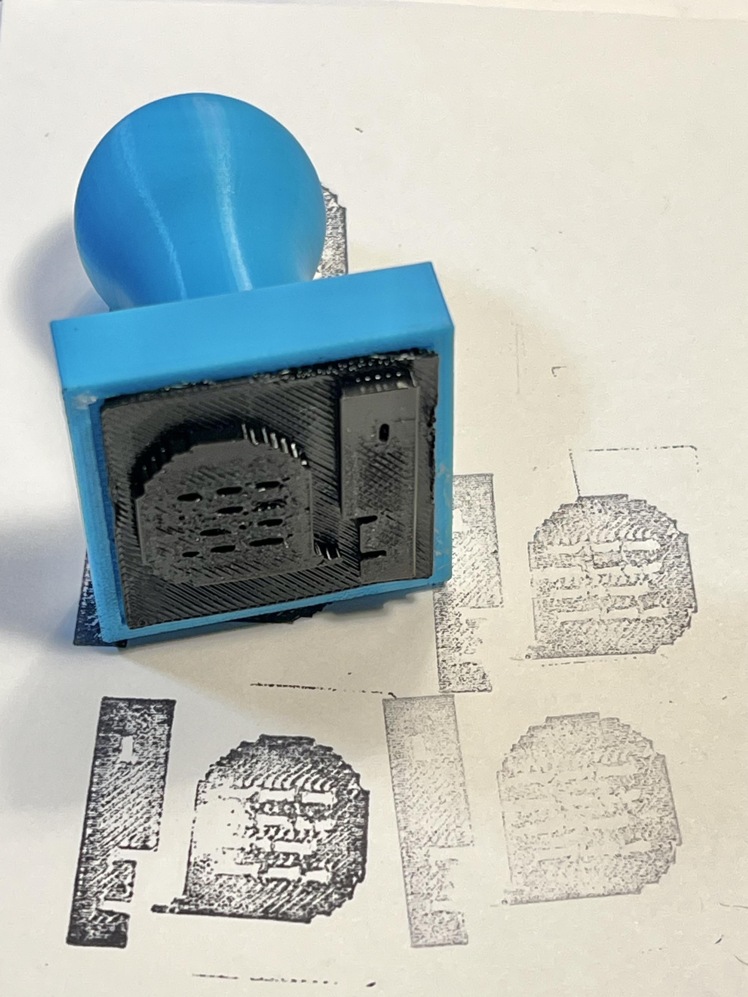
The top of the Maclock includes a touch sensitive area that would turn the backlight on and off, this area marked in red. It doesn’t move, it’s just plastic.
Underneath is a board that is likely difficult to remove, embedded with glue. It has two leads coming off of it.
Without seeing the board, can you theorize how it works and how it could be utilized with a Raspberry Pi GPIO?
-
Mac and TinyMac.
@paulrickards "Don't talk to me or my son ever again."
-
Mac and TinyMac.
@paulrickards I really hoped this was Mac and Massive Mac.
Coming soon?
-
@paulrickards I really hoped this was Mac and Massive Mac.
Coming soon?
@anthony All depends on your perspective 😆
-
The top of the Maclock includes a touch sensitive area that would turn the backlight on and off, this area marked in red. It doesn’t move, it’s just plastic.
Underneath is a board that is likely difficult to remove, embedded with glue. It has two leads coming off of it.
Without seeing the board, can you theorize how it works and how it could be utilized with a Raspberry Pi GPIO?
@paulrickards Attach a Multimeter in Voltage mode (max. 20V) and press the “button” and see what happens?
-
Mac and TinyMac.
@paulrickards the little one was from that clock mac right?
-
@paulrickards the little one was from that clock mac right?
-
Mac and TinyMac.
@paulrickards so what’s inside the regular sized Mac, then? Another Pi with a bigger screen?
-
@paulrickards so what’s inside the regular sized Mac, then? Another Pi with a bigger screen?
@WiteWulf Yeah, a Pi 4 with a 8" LCD and curved acrylic front from this store. I got mine a few years ago, looks like the current ones are 1024x768 and right side up (mine is fixed resolution 1536x2048 and rotated 90 CCW).
I have a history of sticking LCDs in side Mac cases like my SE/30 triple display rig 😄
-
@WiteWulf Yeah, a Pi 4 with a 8" LCD and curved acrylic front from this store. I got mine a few years ago, looks like the current ones are 1024x768 and right side up (mine is fixed resolution 1536x2048 and rotated 90 CCW).
I have a history of sticking LCDs in side Mac cases like my SE/30 triple display rig 😄
@paulrickards oh, very nice!
-
Mac and TinyMac.
@paulrickards wow that’s really cool! Is it possible to buy a tinymac complete?
-
@paulrickards wow that’s really cool! Is it possible to buy a tinymac complete?
@thomas_klopf Not that I know of. Just the parts to DIY.
-
@thomas_klopf Not that I know of. Just the parts to DIY.
@paulrickards thanks! Yeah no time these days for that, but very cool 😎
-
Mac and TinyMac.
@paulrickards@mastodon.social Where'd you get that TinyMac? Never seen that before.

-
@paulrickards@mastodon.social Where'd you get that TinyMac? Never seen that before.
@starlight Made it! See the top of this thread.
-
The top of the Maclock includes a touch sensitive area that would turn the backlight on and off, this area marked in red. It doesn’t move, it’s just plastic.
Underneath is a board that is likely difficult to remove, embedded with glue. It has two leads coming off of it.
Without seeing the board, can you theorize how it works and how it could be utilized with a Raspberry Pi GPIO?
@paulrickards@mastodon.social perhaps grabbing a multimeter, applying some power to the board, and seeing what happens when you activate it? that way you know what sort of signal it sends and when, and can prep for gpio pin interactions that way?
Feed RSS
Gli ultimi otto messaggi ricevuti dalla Federazione
-
@brooke nobody's under any obligation to coach a kid's soccer team, but coaching a kid's soccer team takes 10-20 hours per month.
-
-
@aeva I got a haircut!
-
@brooke often, yes.
-
@mitchellh ok, let me know when it's done.
-
@brooke @mitchellh it's not a secret question. "How much time should one dedicate to maintaining an Open Source project" is really straightforward. It's a practical question about bug triage, dependency management, and maybe making some progress or adding new features. If the question was about mushy bullshit, I wouldn't have given fixed time constraints.
-
@evan @ted forking is always, *always* an option and sometimes *absolutely* the right one for the case where a barely-maintained hobby project gets used by somebody else and it becomes a dependency, unexpectedly to the original author
-
@evan @ted the corollary is that you shouldn't promise maintainership you can't provide.
so if you maintain a project *that people use and you don't have time or inclination to do the work they need* you have two options:
* recommend someone else do it (add maintainers or let them fork it)
* get support so you can do that instead of a different day job