A while back I bought two of those Maclocks with the intention of modding one into a tiny Mac.
Uncategorized
105
Posts
31
Posters
0
Views


-
More #TinyMac progress. Wired up some smol speakers to a smol audio amp.
Designed and printed a volume knob in the style of the original to fit the B50K pot. Biggest issue is how to mount it inside (the amp board has no mounting holes).
The amp turns out to be too noisy, I can hear WiFi and BT traffic. Also draws about 300mA even when the volume knob is switched off.
I think I'll leave it out.
@paulrickards I found exactly the same noise problem with mine. The 3D printer is very nice. I tried filing down the Maclock one to fit in the slot cut in the pot and just wound up snapping it 😔
-
More #TinyMac:
- Swapped in a Raspberry Pi 3A+ for the Pi Zero 2 W. Slightly faster and has 5GHz WiFi which is so much better.
- Mounted the LCD/Pi to the back of the front case with some hot glue.
- Kept the front floppy switch as a power switch when floppy is inserted.
- Installed a LX-2BUPS (2x18650 UPS) inside for power, exposed a USB-C port on the back for charging.
@paulrickards oh, using the floppy switch is a nice touch! Does it do clean shutdown when you eject?
-
@paulrickards oh, using the floppy switch is a nice touch! Does it do clean shutdown when you eject?
@paulrickards love the mounting behind the screen, too. That’s much neater than having it in the case, which I’d been trying to figure out.
-
@paulrickards I found exactly the same noise problem with mine. The 3D printer is very nice. I tried filing down the Maclock one to fit in the slot cut in the pot and just wound up snapping it 😔
@WiteWulf I can post the STL if you want.
Funny, the noise isn't present until you stuff it all inside the case in close proximity to the antennas 🙃
-
@paulrickards oh, using the floppy switch is a nice touch! Does it do clean shutdown when you eject?
@WiteWulf Nothing fancy, it just switches the power to the Pi on and off.
I would love to use the touch sensor on the top of the case for a soft shutdown though! Any ideas what's in the top?
-
@WiteWulf Nothing fancy, it just switches the power to the Pi on and off.
I would love to use the touch sensor on the top of the case for a soft shutdown though! Any ideas what's in the top?
@paulrickards no idea; mine’s held in firmly with hot glue. There are scripts available that trigger a clean shutdown when you put a signal on a GPIO pin. I’m sure you could rig the fdd switch to that.
-
More #TinyMac:
- Swapped in a Raspberry Pi 3A+ for the Pi Zero 2 W. Slightly faster and has 5GHz WiFi which is so much better.
- Mounted the LCD/Pi to the back of the front case with some hot glue.
- Kept the front floppy switch as a power switch when floppy is inserted.
- Installed a LX-2BUPS (2x18650 UPS) inside for power, exposed a USB-C port on the back for charging.
Two tiny Macs, my converted one and an unmodified Maclock.
-
Two tiny Macs, my converted one and an unmodified Maclock.
@paulrickards Now you can write a Maclock emulator to run on the emulated one... 😀
-
Two tiny Macs, my converted one and an unmodified Maclock.
Obligatory flying toasters.
-
Obligatory flying toasters.
-
Obligatory flying toasters.
@paulrickards
but can you make the toasters leave the left-screen and pick up (exactly) on the right? 🤔
* the first time I saw that was on an attached Two Page Monitor for SE/30 in 1990 ... and I almost fell over because someone else installed it, and the timeout was really long so it had never "kicked in" -
@paulrickards
but can you make the toasters leave the left-screen and pick up (exactly) on the right? 🤔
* the first time I saw that was on an attached Two Page Monitor for SE/30 in 1990 ... and I almost fell over because someone else installed it, and the timeout was really long so it had never "kicked in"@petabites Multiple monitors was absolute magic back then.
No idea if Basillisk II supports addition displays.
-
Obligatory flying toasters.
@paulrickards very cute. Almost therapeutic:)
-
Obligatory flying toasters.
The top of the Maclock includes a touch sensitive area that would turn the backlight on and off, this area marked in red. It doesn’t move, it’s just plastic.
Underneath is a board that is likely difficult to remove, embedded with glue. It has two leads coming off of it.
Without seeing the board, can you theorize how it works and how it could be utilized with a Raspberry Pi GPIO?
-
The top of the Maclock includes a touch sensitive area that would turn the backlight on and off, this area marked in red. It doesn’t move, it’s just plastic.
Underneath is a board that is likely difficult to remove, embedded with glue. It has two leads coming off of it.
Without seeing the board, can you theorize how it works and how it could be utilized with a Raspberry Pi GPIO?
@paulrickards Touch sensitive and "two wires" to me smells like it's literally just a bare capacitive sensor, with all the sensing smarts being on whatever it's connected to. (one wire being GND and the other being 'sense')
-
The top of the Maclock includes a touch sensitive area that would turn the backlight on and off, this area marked in red. It doesn’t move, it’s just plastic.
Underneath is a board that is likely difficult to remove, embedded with glue. It has two leads coming off of it.
Without seeing the board, can you theorize how it works and how it could be utilized with a Raspberry Pi GPIO?
@paulrickards Capacitive touch sensor ?
-
@spacehobo @paulrickards but with only two wires to the board that's tricky if it's anything other than just a pair of pads for a touch sensor.
-
The top of the Maclock includes a touch sensitive area that would turn the backlight on and off, this area marked in red. It doesn’t move, it’s just plastic.
Underneath is a board that is likely difficult to remove, embedded with glue. It has two leads coming off of it.
Without seeing the board, can you theorize how it works and how it could be utilized with a Raspberry Pi GPIO?
@paulrickards does it just function like a momentary switch, by chance?
-
The top of the Maclock includes a touch sensitive area that would turn the backlight on and off, this area marked in red. It doesn’t move, it’s just plastic.
Underneath is a board that is likely difficult to remove, embedded with glue. It has two leads coming off of it.
Without seeing the board, can you theorize how it works and how it could be utilized with a Raspberry Pi GPIO?
@paulrickards if not touch capacitive, could be an IR led & photoresistor in series. The toucher reflects the IR back, reducing the resistance and increasing the circuit's current flow. Not sure if that could be measured over just two wires going to a Pi's GPIO pins. This method of "touch" sensing probably needs more signal processing than capacitive touch, but it's not the worst way to do it

-
Obligatory flying toasters.
@paulrickards I’m looking forward to my über-portable AIR router project once my Maclock arrives. I also bought a pre-made-but-3D-printed-case mini Mac to maybe shortcut things.
Feed RSS
Gli ultimi otto messaggi ricevuti dalla Federazione
-
@CassandraVert That's a nice company you've got there, sure would be a shame if something happened to it.
-
@billyjoebowers Same technique that he has with no longer releasing unemployment figures. But at least Gallup, the rat fucking cowards, is not the only polling organization.
-
Were they threatened?
-
@mitchellh cool. So, can I have admin access to all your repos? I can't commit to any amount of time, but I still want to be a maintainer. I'm evanp on GitHub.
-
@billyjoebowers Sounds more like a gift to Trump who will no longer be reminded regularly of how badly he is performing. Perhaps it is a spin on having to respond to a threat of sorts by the Administration. One day, all will be revealed.
-
@evan okay so you are asking about when one should deem a project "unmaintained".
Depends entirely on the project.
Also while you are centering project volunteers, the judgment is one that necessarily must be made by downstream users, not by the alleged maintainers.
(Though it's fine and helpful to say "hey this project is now unmaintained, just FYI".)
-
@tess if you don't think the question has an answer, feel free to skip it.
-
@tess right, and at some point you are not maintaining the software.
It's not about whether people have a right to demand that you do the job. The question is about how much time the job takes.
Post suggeriti
-
-
30 settembre 1988 #accaddeoggiIBM annuncia la spedizione di 3 milioni di personal computer PS/2, successori di PC, XT e AT.
Uncategorized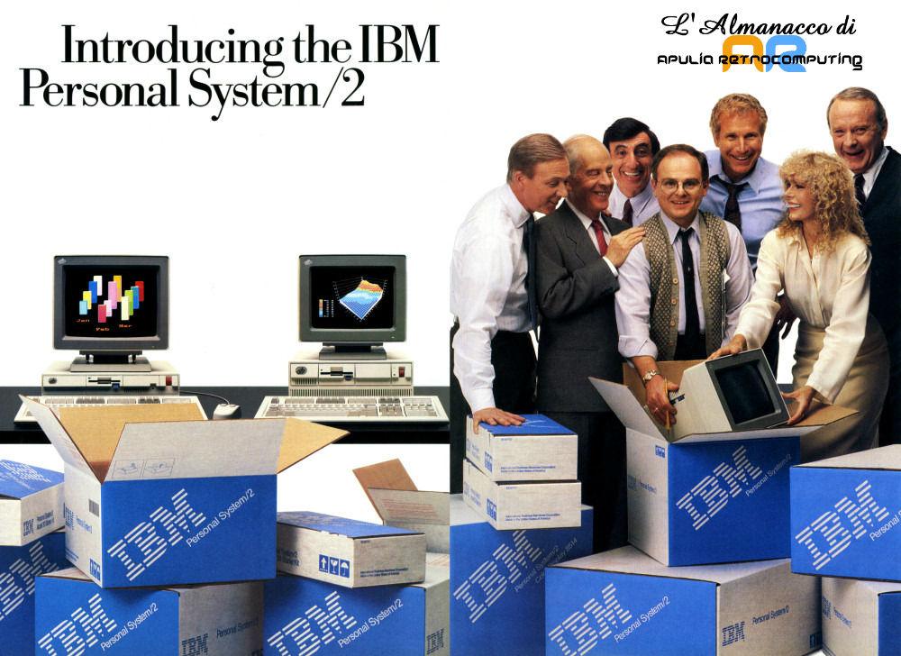 1
1
-
𝗖𝗢𝗠𝗠𝗢𝗗𝗢𝗥𝗘 𝟲𝟰 𝗨𝗟𝗧𝗥𝗔 𝗖𝗢𝗡𝗩𝗜𝗡𝗖𝗘: 𝗕𝗢𝗢𝗠 𝗗𝗜 𝗩𝗘𝗡𝗗𝗜𝗧𝗘 𝗘 𝗔𝗖𝗤𝗨𝗜𝗦𝗜𝗭𝗜𝗢𝗡𝗘 𝗔𝗡𝗧𝗜𝗖𝗜𝗣𝗔𝗧𝗔 𝗗𝗘𝗜 𝗠𝗔𝗥𝗖𝗛𝗜Appassionati e collezionisti confermano il forte legame emotivo col celebre home computer degli anni '80
Uncategorized 1
1
-